Pro-Tech 7208 Especificaciones
Busca en linea o descarga Especificaciones para Sierras circulares Pro-Tech 7208. Pro-Tech 7208 Specifications Manual de usuario
- Pagina / 36
- Tabla de contenidos
- MARCADORES

Indice de contenidos
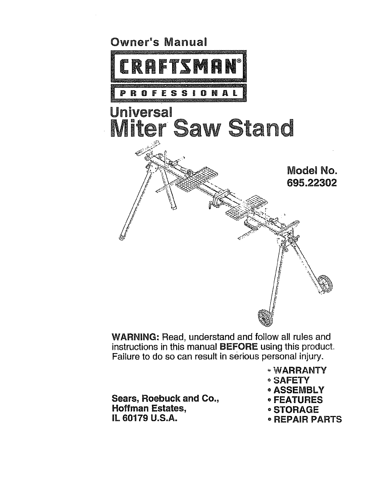
Owner's ManuaUModel No.695.22302WARNING: Read, understand and follow all rules andinstructions in this manual BEFORE using this product,.Failure
FAILURE TO HEED ALL SAFETY AND OPERATINGINSTRUCTIONS AND WARNINGS REGARDING USE OF THISPRODUCT CAN RESULT IN SERIOUS BODILY INJURY,Tools Needed, #2 Ph
NSTALL WHEEL BRACKET ASSEMBLIESFigures 6 - 8)Fig. 6M,_r_[_ct locations for wheel support assembhes are fdentJfied by the_,,p_._)iate sticker on the fa
INSTALL WHEEL BRACKET ASSEMBLIES, cont.Mount wheel support assemblies (M) and (N) to ends of connector bracketson frame using pan-head screws (3"
UNFOLD AND LATCH FRAME(Figures 9 and 10)Unfold frame by releasing snap lock and rotating frame sections apartuntil aligned. See Fig. 9.Fig. 9Release s
UNFOLD LEGS(Figures 11 and 12)Unfold legs by disengaging locking pins and rotating the legs until thelocking pins snap into the open position, If depr
INSTALL EXTENSION KNOBS(Fi'gures 13 and 14)Locate extension spacer nuts and align with holes in frame as shown.Thread extensionknob assemblies (J
INSTALL SUPPORTS(Figures 15 and 16)Fig. 15L (two)tPosition a support connector (K) on end Of each extension and tighten Phillips-head screw to secure.
INSTALL EDGE GUIDES(Figures 17 - 20)Fig. 17H(two)(preinstalled) (preinsta!led)Two sets of edge-guide mounting screws (R) and nuts (S) are preinstaledo
INSTALL EDGE GUIDES, cont.Position edge guides (H) over nuts (S) and secure using screws (R).Figure 19,Fig. 19SeeSEdge guide may be positioned as desi
INSTALL CLAMPING SYSTEMFigures 21 - 23)Fig, 21G(two)Slot nAlign slot nut of clamp (G) in center frame slot. Rotate clamp so tab fitsinto slot. Repeat
Warrant-j... ,.Safety Instructions.._... ,... ...Description, Specif
INSTALL CARRYING HANDLE(Figures 24 - 26)Fig. 24D U (two)Locate the two nuts in the front slot on right side of stand, as shown in Figure25. For best b
INSTALL WHEELS(Figures 27 = 30)Install whee! assemblies (B) by pressing axles into wheel brackets.See Figure 27.Fig. 27Wheels may be installed in eith
iNSTALL WHEELS, cont.For transporting short distances while stand is set up, wheels may be:_laced in the lower position. See Figure 29.Fig. 29Before c
ADD MOUNTING BOARDS(Figures 31 and 32)Fig. 31c (two)Place two mounting boards (C) on stand, slots on top and toward theoutside of stand. See Figure 32
MOUNT THE MITER SAW(Figures 33 - 38)MOUNTING THE MITER SAW TO'THE BOARDSSecure boards to frame of miter saw stand as explained in "ADDMOUNTI
MOUNT THE MITER SAW, cont.MOUNT THE MITER SAW TO THE BOARDS, cont.Fig. 34Fig. 3525
MOUNTTHE MITERSAW, cont.ADD RUBBER FEETTO BOTTOM OF MOUNTING BOARDS(Figures 36 and 37)Remove boards from stand and drill two pilot holes for Screws (W
Fig. 3827
This workstand is designedfor usewith Craftsman and mostotherbrands of miterand compound miter saws. The saw willmountdirectly to the boards provided
Mounting Non-Standard Miter Saws and Other Tools To The Boards •(Figures 39 and_O)" ';_ '_ "'_'! _' ,NOT_0UNT A TAB
1. DO NOT standor climb on miter saw stand, it couldtip overcausing serious injury.2. BE SURE all locking pins are in the set-up position holes BEFORE
USING THE STOCK SUPPORTS(Figure 41)Two stock supports are located under the frame of the table. These maybe pivoted out to support work pieces as desi
USING THE WORK SUPPORTS(Figure 42)The two work supports are useful for:!) Vertical support of workpieces2) Positive stops for repetitive cutsTo use th
USING THE EDGE GUIDES(Figure 4-3)The two edge guides are useful for maintaining orientation angle ofworkpieces, such as cove and crown molding.To posi
STORAGE INSTRUCTIONS(Figure 44)Before moving or storing your miter saw stand:Remove power tool and mounting boards from stand.Move wheel assemblie s t
PARTS LISTUniversal Miter Saw Stand Model No. 695.22302Saw-mountinghardware161725S10KEYNO, ITEM PART NO.1 A2 B t19 8O0 8123 C 117 910 0104 D !16 60072
PARTS LISTUniversal Professional Miter Saw Stand Model No. 695.22302KEYNO. PART NO.REPLACEMENT PARTS DESCRIPTION2 119 800 812 Wheel assembly3 117 910
i:!;_J,_ _ 1_' i_" "; ,_ * i_, _ ;- : "-'_:_ '':• _ "" _ • • .,_ i• ',:_,,'_'_, ;: _ _._ i
ELECTRICAL SAFETY1. Double insulated tools are equipped with a polarized plug (one bladeis wider than the other). This plug will fit in a polarized ou
PERSONAL SAFETY (cont.)4. ALWAYS remove adjusting keys or wrenches before turning thetooJ on. A wrench or a key that is left attached to a rotating pa
This Miter Saw Stand is designedwith featuresthat make usingyour mitersaw moreconvenient.The Quick-jaw_ clampand mountingboardsaccommodateand secure m
UNPACKINGUnpack all parts and carefully separate parts from packing materials.Check each part with the parts illustration and list on pages 7, 8 and 9
PACKAGE CONTENTS AND HARDWARE(Figure 3)Item De_scr_ption QuantityJKLMNPQExtension Knob AssemblyWork Support ConnectorWork Support Connector KnobWheel
PACKAGE CONTENTS AND HARDWARE (Figure 4)Item Description " " QuantityR Edge Guide-Mounting Pan-Head 4Screw (M8x16) (preinstalled) •S Edge Gu
Mas documentos para Sierras circulares Pro-Tech 7208


Relacionado con productos y manuales para Sierras circulares Pro-Tech 7208
 (60 paginas)
© 2020, manymanuals.es. Todos los derechos reservados | 0.029 s |
 Manymanuals.com
 Manymanuals.de
 Manymanuals.fr
 Manymanuals.it
 Manymanuals.pl
 Manymanuals.cz
 Manymanuals.es
 Manymanuals-pt.com
Comentarios a estos manuales